

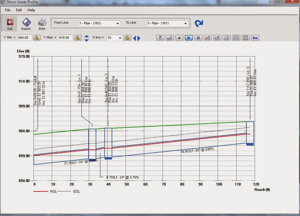
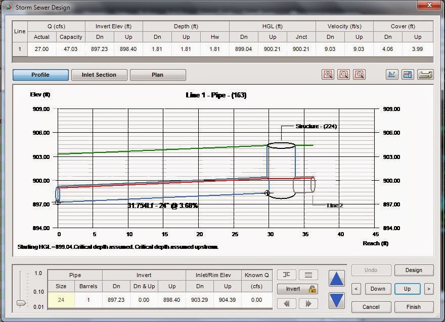
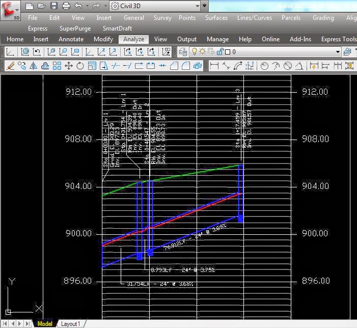
Hydraflow Storm Sewers has the ability to calculate the Hydraulic Grade Line (HGL) and show it graphically in profile. With this application, youcan export a profile with the HGL value as a DXF file that can be manipulated in Civil 3D. A profile would appear something like what you see here. The red line represents the HGL value, and the green line is the ground surface.
Exporting a pipe network from Civil 3D to Hydraflow Storm Sewers

 Open Civil 3D,
Go to the analyse tab and select the "Edit in Storm Sewers" button.
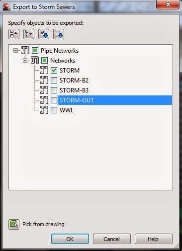
You will be asked to select the pipe networks you would like to analys in Hydraflow Storm Sewers
It will promt you for a Hydraflow Storm Sewers file name.
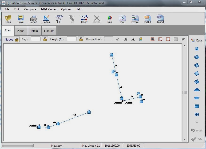
Hydraflow Storm Sewers will then launch
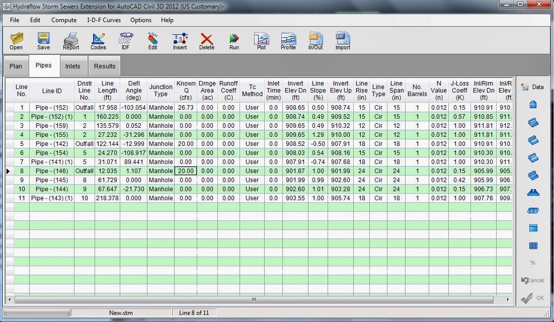
Data for the pipes and inlet can be added or edited in table format. Clicking the Pipes or Inlets tab at the top of the main screen takes you to a table in which you can edit values as necessary.
After running the calculation, you can easily make additional adjustments to pipe sizes and inlets with the interactive design feature in Hydraflow Storm Sewers. As shown in the preceding illustration, the default display is a profile view of the pipe. Using the controls, you can manipulate the slope, size, and even Q values. You can also scroll through multiple pipes to make changes along the entire network. The interactive display has three different sections: Profile view, Plan view, and Inlet Section.
Several different calculation scenarios are possible. The Compute System dialog box appears when you use the Run button to begin your calculations. As you can see, within Hydraflow Storm Sewers four calculation options are available to help you distinguish between the varying conditions and possible results. The most commonly used option is Analysis w/ Design; it holds any data you choose to add and calculates any values that are not specified. This analysis starts at the downstream and works upstream.
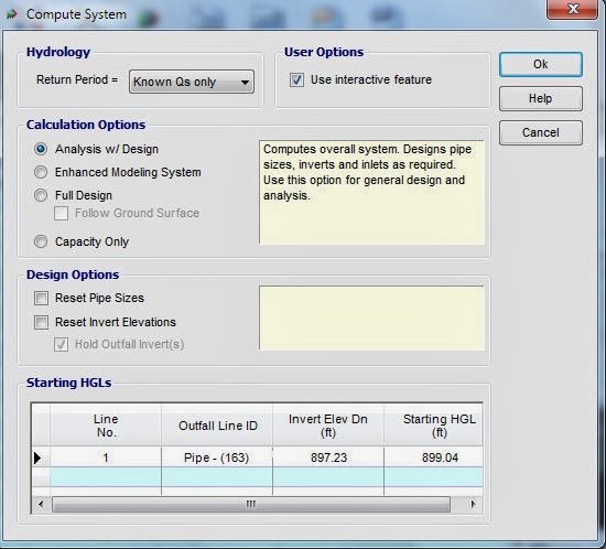 In addition, other options in the Compute System dialog box enable you to automatically reset all the current pipe sizes, invert elevations, or both. If you have a known starting hydraulic grade line (HGL), you can also enter that value here, or select one of the other options.
Hydraflow Storm Sewers has the ability to calculate the HGL and show it graphically in profile. With this application, you can export a profile with the HGL value as a DXF file that can be manipulated in Civil 3D. A profile would appear something like what you see here. The red line represents the HGL value, and the green line is the ground surface.
Exporting Hydraflow Storm Sewers files to Civil 3D
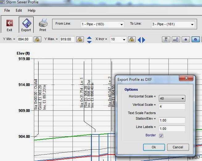
When you are satisfied with your analysis, you can export the revised layout to DXF by clicking the In/Out button you saw earlier. The Import/Export DXF dialog box has a separate tab for Export. You can export DXF as a new file or to update an existing DXF file.
Then, when you are ready to import your design into Civil 3D, you use the Import DXF command and select a new DXF name (for a new file) or select the existing DXF file that you are updating. If you import a new DXF file, a second network is added to your drawing, so you will most likely want to delete the previous layout and replace it with the revised one.
Then you can copy the HGL over to your current Civil 3D profile.

If you have adjusted the pipe sizes and slopes and would like to have Hydraflow Storm Sewers automatically updated your Civil 3D profiles, then
you can also export the revised layout to LandXML by clicking the In/Out button you saw earlier.
The Import/Export LandXML dialog box has a separate tab for Export. You can export LandXML as a new file or to update an existing
XML file.
Then, when you are ready to import your design into Civil 3D, you use the Import LandXML command and select a new LandXML name (for a new file) or select the existing LandXML file that you are updating. If you import a new XML file, a second network is added to your drawing, so you will most likely want to delete the previous layout and replace it with the revised one.
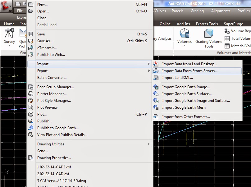 You can also import the Hydraflow Storm Sewers .stm file from Civil 3D by going to File> Import > "Import Data from Storm Sewers".
It will promt you for a .stm file.
Your Civil 3D profiles will be automatically updated with your Hydraflow Storm Sewers data.
In addition to drawing sets, you may also be required to submit calculations in the context of a report. Hydraflow Storm Sewers Extension offers options for creating reports specific to the HGL calculations, inlets, Tc, and so forth. Results can also be exported as text files.

Hydraflow Storm Sewers Extension provides the capability to perform storm sewer design and analysis tasks that are necessary in civil and environmental engineering. The availability of this extension adds important technology to the Autodesk civil engineering solution that will enable Civil 3D customers to address a crucial part of their workflow as well as get higher value from design information for predicting project performance.
Drain problems? Not anymore! Call Bronx Drain Cleaning today.
ReplyDelete